As I wrote in my last post I’ve started using a new exciting mode on HF, but that’s not the only thing that’s new. A friend of mine, also a hamradio operator, was getting rid of one of his vertical antennas. As I’ve mode some experiments with a homebuilt quarterwave vertical before and was a bit curious of the construction of wideband verticals, I decided to buy it and make some tests.
The antenna is a Wimo GPM-1500 and is marketed as a wideband antenna covering 1.8 to 30MHz requiring a tuner for matching. Looks like a quite good antenna does it? Well, I as a bit doubtful that it would really be as wide banded as stated, partly from my own experience with building and measuring antennas and also from the theoretic point of view. I decided to make some measurements on the new antenna to see how wide banded it is observing the the SWR value.
For the SWR measurements I used my newly purchased antenna analyzer, the Rigexpert AA-30, measuring 0-30 MHz and a RG-58 cable for connecting to the antenna.
So I started setting up the antenna, mounting it on ground level about 50 cm of the ground on a steel pipe with no ground radials. The antenna is said to require ground radials to operate efficiently but can be operated without.
GPM-1500 @ groundlevel, no radials
The output from the AA30 showed the following values:
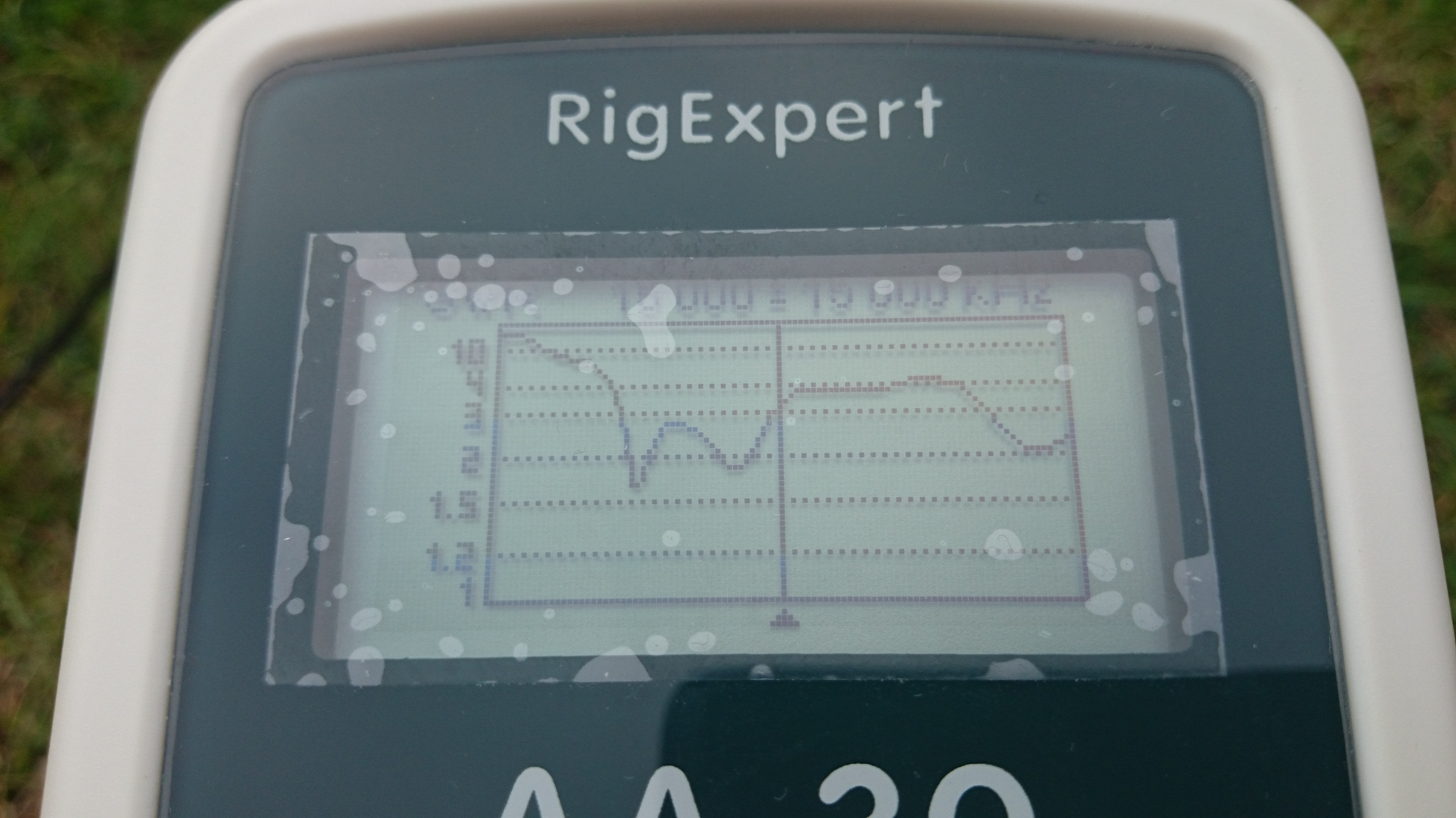
First measurement, no radials, steelpipe mounting
As shown the SWR never dips down under 1,5. Although the SWR stays mainly about 4 and under most of the HF band. A built in tuner may be able to handle this and it seems like it may be usable on high frequencies over 30m band but on the lower bands it´s a nightmare.
I now tried to raise the antenna a few meters, because of the risk of touching the feedpoint and the antenna itself when mounted in the garden. I found a wooden pole with a length of about 2m. I mounted the antenna and it is now “free floating” without any ground connection.

Second measurement, wooden pole 2m, no radials
Now the curve have become about the same as before but with a dip somewhere in the 20 m band area. Still not good in the lower bands and the higher is still around 4 with a dip in the 10 m band. The next step is to reconnect the antenna to the ground by using a braided copper band and a 1 m copper piece driven to the ground. This may not be a perfect ground but it is useful just to see how it affects the properties of the antenna.

Antenna mounted on a wooden pole, connected to the ground with copper band.

Third measurement with ground connection, no radials
This time the curve shows that the dip in the 20 m band is gone but is now widened with a value under 2 wich can be handled by a built in tuner. Lower frequencies are still bad and higher is still the same with a reduced dip in the 10 m band.
As I wanted to reduce the SWR value in the lower bands I now tried to connect a radial roughly in the 40 m band area, hoping that it may effect the curve. I also disconnected the grounding with the copper band as it had no effect on the lower bands.

Copper braid disconnected and radial connected.
I decided to lay the radial on the ground as it is impractical with elevated radials with this length in my garden.

Forth measurement, 40 m radial
The curves show no real improvement on the lower frequencies. More radials with the same length was connected later on but it showed no improvement as well.
I decided to stop my experiment at concluded that the antenna, as it is in my garden, is useful for 30 m band and up. Lower bands is to hard to match. I had a number of radials used for my old 20 m experimental vertical that i connected to the new antenna. They were mounted as elevated radials at roughly 45 degrees angle down to the ground. I also bought some steel tubes pushing the feedpoint of the antenna to a height of 3 m. The combination of 20 m radials and the ground connection of the steel tubing resulted in a deep dip in the 20m band with a SWR value of 1.1 and leaving the higher frequencies between 4 and 2. The lower bands are still bad.

The final result of steel tube mounting and radial system for 20 m band.
In it´s current configuration the antenna is useful as a listening antenna for the HF bands and a transmitting antenna for 20 m band. Even though it is useful in transmitting from 30-10 m I´m choosing to use my more efficient Inverted V antenna for transmitting. I am planning to continue with grounding and radial experiments to try to make the antenna useful in the lower bands, at least down to 40 m.
My conclusion about this antenna is that, as expected, it is a typical wide band antenna that is a compromise to make it work at as many bands as possible. The compromise is in the matching, meaning that it is more or less good matched depending on the frequency but is tunable with a riggs internal tuner. As with other verticals, the risk of RF feedback is high when the matching is not good.
In my complete station configuration it´s a good compliment, despite it´s downsides. The use of a different type of antenna located at a number of wavelengths from the main antenna makes it a good reference antenna with somewhat antenna diversity feature for incoming signals.
73
//Anders

Hi Anders,
Thanks for this information about this Antenna.
You are right indeed – I ve made exactly the same experience.
Built some short dipoles, they all were better than GPM 1500. So I cannot believe Wimo is declaring the usability from 1.8 to 50MHz.
OMG.
But I guess this is an usable portabel ant, because easy and quick to built Up.
Thats I want you to know.
Stay healthy & 73 from Ted, DM3RCK