The portable QRP project is moving forward and I’ve started to look at putting it all together.
I have started to focus on the power supply for the portable kit. The battery of choice is a cheap lead type battery with a nominal voltage of 12V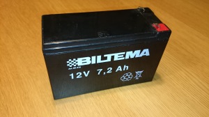 and has 7.2Ah capacity. The battery and a suitable AC charger was purchased a while ago with battery backup functionality in mind but may be found useful also in this portable kit. I have two main consumers to the battery, the computer and the transceiver. The transceiver is operational on 12V DC why it shouldn’t be any problem connecting it directly to the battery.
The computer on the other hand is operating on 19V DC which makes it a bit complicated. To connect the computer to the same power supply as the transceiver, I need a DC/DC converter to supply the correct voltage.

I’d remembered noticing a sales add at a well known Swedish electronics accessories dealer having a sale on car accessories for laptop computers. A suitable converter along with a wide range of connectors was purchased for about 10€. Now I have the voltage conversion problem solved. The converter may come in handy in other applications as well.
Now when all the unit have the correct voltage and is ready for 12V operation I started to look at the expected operational time for the solution. To make an estimation on how long the operational time will be, I have to make some measurements on the current drain on both of the computer and transceiver. The transceiver was hooked up to a power supply with a ampere meter in serial with 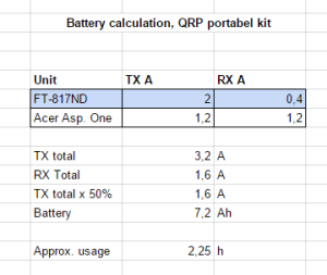 the positive lead and was measured at RX and 5W TX @ CW. The transceiver showed a drain of appr. 2A in TX and 0.4A in RX. The same thing was done with the computer connected with the DC/DC converter and the Signalink USB plus a CAT-cable. The result was that It had a drain of ca 1.2A constantly. To do the calculation I made a quick Excel document with a formula specifying the typical operation. I calculated a TX cycle of 50% which means that half the time the transceiver will be in TX and half in RX. Now, this may vary depending of which digital mode i wish to operate as well as the number of QSO:s being made. For JT-modes the cycle is close to 50% as you transmit and receiver half the time. When the calculation was done the result showed an estimated operation time of 2.25h. The calculation is however not exact enough as there are some factors that I haven’t included. An estimation gives that in reality I only should have about 1 to 1,5h of operation with the TX cycle above. This may require me to adjust my operational techniques to prolong the operational time.
Now, to connect it all together to the battery I had some thoughts about how to do this. As the DC/DC converter comes with a cigarette lighter 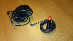 connector, it seems stupid to cut this of. The converter Is also useful in the car when using the computer mobile. One of my findings in the junk box was a power connector divider for cigarette lighter connectors. The use of this allows me to retain the connector on the converter and add one to the transceivers DC-cable, making the kit also useful for mobile operation as well.
I now feel that I have the power supply solution ready for testing. All I have to do is set the battery on charge and set it all up after it´s ready…
73 de SM7VRZ

Leave a comment